

When you look at a power system, the big stuff gets all the attention- the breakers, the massive power transformers, the switchgear. But tucked away in the metering cabinets and relay panels, there is a hero doing the quiet work of keeping the lights on and the equipment safe: the potential transformer. While often mentioned in the same breath as its cousin, the current transformer (CT), a potential transformer has a completely different job.
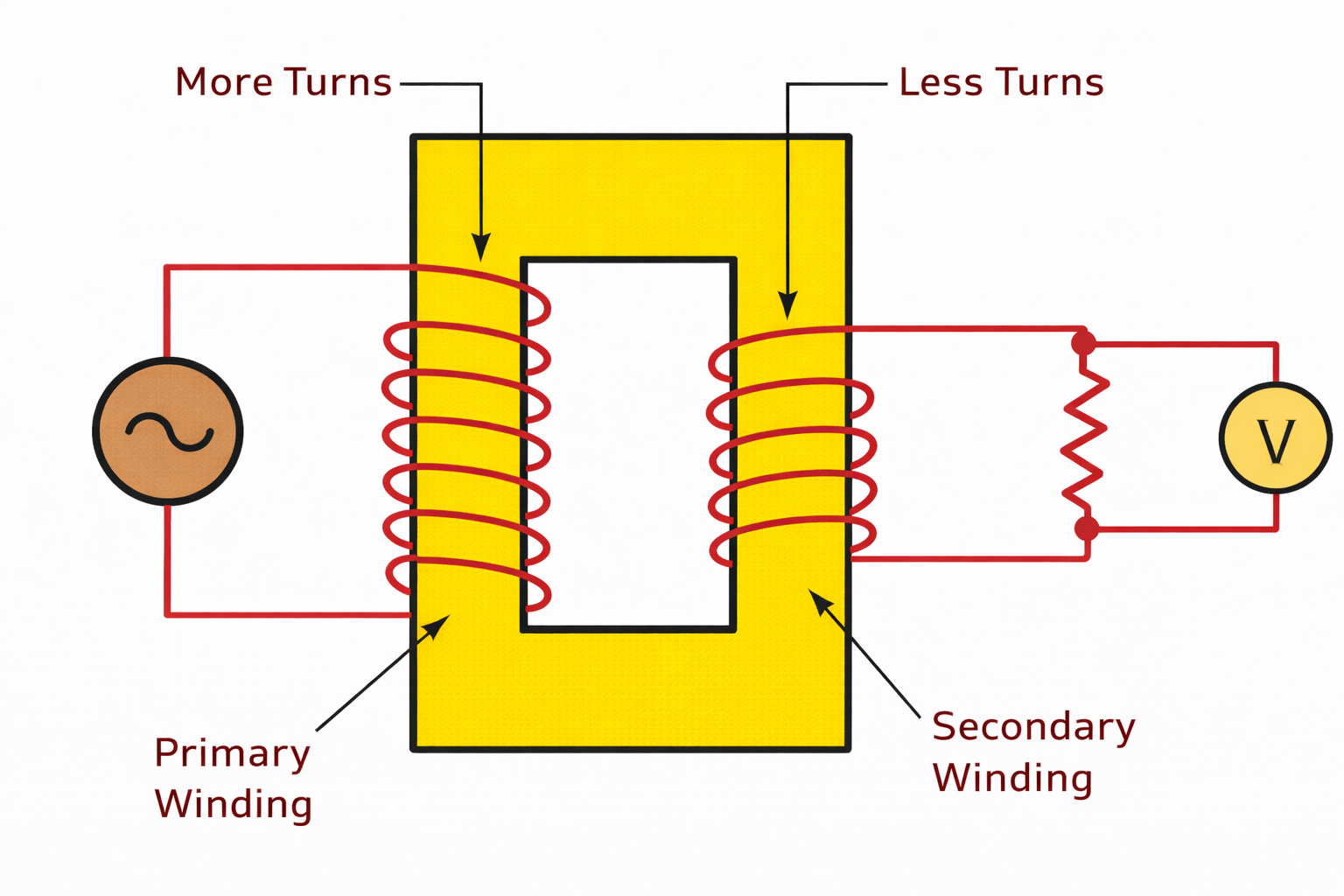
A CT is a series transformer that steps down current and acts like a mirror reflecting the line current at a manageable level. A potential transformer is a parallel device that directly connects across the power line to supply a reduced-voltage replica of the system voltage for precise metering and protection schemes.
The thesis of a well-built potential transformer is simple to state but difficult to achieve. It must provide voltage fidelity within strict tolerances while maintaining structural integrity for years, often in places where the elements cannot take even a coffee break.
The Environmental Gauntlet
A spec sheet tells you what a potential transformer does in a lab at room temperature. Real life happens outside that building. Imagine a unit installed in a fenced-off field or a coastal substation. Over twenty years, it will bake in direct sun, shiver through sub-zero nights and get pelted with rain, salt fog and industrial pollution.
Temperature swings are a silent enemy of accuracy. The magnetic properties of the core can shift as the materials inside the potential transformer expand and contract. This affects the turns ratio and the phase angle and introduces errors into billing meters that should not exist. Then comes moisture and contamination. When salt spray or industrial grime builds up on the surface of a bushing, a path is created for leakage current. If the insulation system isn’t designed to handle this, it degrades over time. This is why the physical construction and encapsulation of a potential transformer are just as important as the core steel inside.
And do not forget the vibration. A potential transformer mounted near switching gear or in an area with frequent seismic activity (or even heavy truck traffic) experiences mechanical stress. Those stresses, if not accounted for in the design, can eventually fatigue the internal connections or cause microscopic cracks in the insulation.
Core Design Choices for Lasting Fidelity
To survive that gauntlet and still provide accurate readings, the design of a potential transformer has to be intentional from the inside out.
The journey starts with the core material. Using high-grade silicon steel helps guarantee low hysteresis loss. This means the core doesn’t waste energy heating up every time the magnetic field reverses, which keeps the transformer running cooler and the voltage ratio stable. The choice here dictates how well the potential transformer maintains its accuracy class over a full 24-hour load cycle.
The insulation system does double duty. It must provide the dielectric strength to withstand high voltage transients (like lightning strikes), but it also acts as the first line of defense against moisture ingress. Outdoor-rated potential transformers often use UV-resistant cycloaliphatic epoxy resin for this reason. This material handles solar radiation and high humidity without tracking or cracking.
Thermal management is the third leg of the stool. Even the most efficient core generates some heat, especially when the voltage is high. Engineers choose specific wire gauges and core geometries to make sure that internal heat dissipates properly. If a potential transformer runs too hot, the insulation ages faster and the copper resistance changes. This throws off the phase angle.
Manufacturing Precision
You can have the best design in the world on a whiteboard. However, the field performance will be a lottery if the shop floor cannot build it the same way twice. This is where process control enters the picture. While following ISO 9001 protocols equals paperwork, the focus is more on traceability and repeatability. Every winding, every termination and every encapsulation pour has to follow a verified procedure so that the unit coming off the line in December performs exactly like the unit that passed testing in June.
Before a potential transformer ever ships, it goes through a battery of tests. The hi-pot test verifies that the insulation can handle momentary overvoltages without breaking down. But the more revealing tests are the accuracy checks. Here, we simulate the actual burden (the load from the connected meters and relays) that the potential transformer will see in the real world. We run the voltage up and down, measuring the ratio and phase error to confirm it meets the specified class. This real-world simulation is the only way to catch issues that a simple bench test might miss.
Conclusion
In the world of power measurement, durability and accuracy are not two separate goals. They are two sides of the same coin. A potential transformer that loses its accuracy due to environmental stress is just as useless as one that fails electrically. Designing for the real world means respecting both the physics of electromagnetism and the brutality of nature.
Do you have a metering or protection application where the environment is less than forgiving? Contact Custom Magnetics to discuss your specific application requirements. We can help you select or design a potential transformer that delivers the voltage replica you need, year after year.


")